
![Telephone Inquiries|81-53-401-5316[office hours 9AM to 6PM]](../image/common/header_tel.gif)


X-ray Line Sensor Camera

LINE SENSORS PROVIDED WITH IDEAL SPECS TO MATCH THE CUSTOMER’S LINE EQUIPMENT THIRD GENERATION X-RAY LINE SENSOR CAMERAS ARE NOW ON THE SCENE!
These have come into wide use since 2003. X-ray line sensor cameras from ImageTech are now third generation devices.
Sharp, clear images can now be captured thanks to developing low-noise circuits for improving the signal-to-noise ratio. The devices can now operate just from a 24 volt DC supply in a move to make the devices more convenient for customers. Moreover, we can provide these cameras in specifications that are ideal for customer needs provided we know the inspection width, conveyor speed and resolution that the customer requires.

Inspection Applications
- Product safety inspections (abnormality inspections for nails in shoes, abnormality inspections of automotive parts, abnormality inspections of steel cord in tires, etc.)
- Baggage inspections (airports, banks, exhibits, concert halls, etc.)
- Inspections for foreign objects (in foodstuffs, pharmaceuticals, clothing, etc.)
- Quantity inspections (sweets, pharmaceuticals, foodstuffs, etc.)
- Inspections for items inside aluminum wrappings that are impossible to sense with metal inspection devices

CT-3i Series Features
-

- Supports a wide ranging area from 50mm to 1600mm to match the inspection object
- Supports a wide ranging area from 50mm to 1600mm to match the inspection object
-
We can provide an x-ray line sensor camera having the ideal range to match the object for inspection.
Check out these inspection object sizes
Bottle caps 50mm
Suitcases 650mm
Wooden structural sheets 1000mm
-

- Optimal pixel size is selectable to match the inspection items
(02.mm• 0.4mm • 0.8mm) - Optimal pixel size is selectable to match the inspection items
(02.mm• 0.4mm • 0.8mm) -
Device elements in all standard cameras are replaceable to give an ideal resolution that matches the object for inspection. Line sensor elements loaded in the camera have 3 types of resolution. All elements can be loaded in the camera.
Pixel spacing is selectable from 02.mm• 0.4mm • 0.8mm.
Check out these inspection object sizes
Semiconductor substrates use 0.2mm element
General foreign object inspections use 0.4mm element
High-speed conveyor lines use 0.8mm element
- Optimal pixel size is selectable to match the inspection items
-

- Line speed double that of conventional models!
Conveyor speeds from 0.1m/minute to 170m/minute - Line speed double that of conventional models!
Conveyor speeds from 0.1m/minute to 170m/minute -
Select a suitable line speed by mounting a matching element in the camera.
Captures images within the short time required on production lines.
- Line speed double that of conventional models!
-

- Camera needs only 2 connector cables
A power cable and a camera link cable - Camera needs only 2 connector cables:A power cable and a camera link cable
-
Supply voltage is just one 24 volts DC system
Needs no dedicated power supply. For example you can use it jointly with the PLC power supply.
Camera signal is the camera link output (Base Configuration)
Can utilize a standard cable.
- Camera needs only 2 connector cables
-

- Providing SDK for developing software for 64 bit OS environments
- Providing SDK for developing software for 64 bit OS environments
-
We provide SDK to support development of customer application software on 64 bit OS environments. We give even more efficient support by providing sample programs.
• SDK is an abbreviation for Software Development of Kits

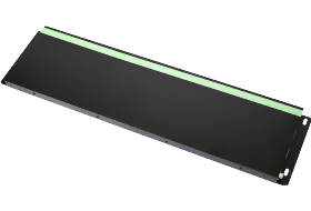
Camera external dimension outline drawing
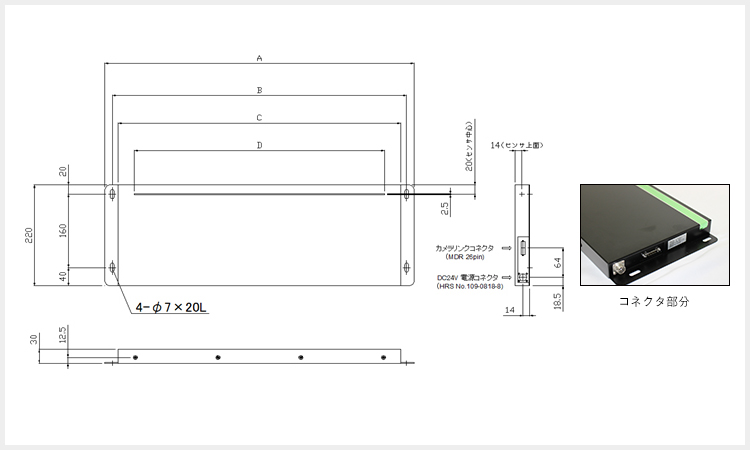

Camera model external dimension table
| A | B | C | D | |
|---|---|---|---|---|
| CT-253 | 375 | 345 | 320 | 257 |
| CT-303 | 430 | 400 | 375 | 308.5 |
| CT-353 | 480 | 450 | 425 | 359.5 |
| CT-403 | 530 | 500 | 475 | 410.9 |
| CT-453 | 580 | 550 | 525 | 462.2 |
| CT-503 | 635 | 605 | 580 | 513.5 |
| CT-553 | 685 | 655 | 630 | 564.8 |
| CT-603 | 735 | 705 | 680 | 616.1 |
| CT-653 | 785 | 755 | 730 | 667.4 |
| CT-703 | 840 | 810 | 785 | 718.7 |
| CT-753 | 890 | 860 | 835 | 770 |
| CT-803 | 940 | 910 | 885 | 821.3 |
(units in mm)
•CT-□□3 model number notation indicates: light sensing area (25=250mm) to (80=800mm).
•In the case of a light sensing area of 50mm to 250mm the joint model number used is CT-253.

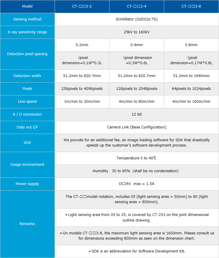
Lineup & Spec Chart
Standard product single line specifications
Allows selecting from among 3 types of detection pixel spacings for product.
| Model | CT-□□3-2 | CT-□□3-4 | CT-□□3-8 |
|---|---|---|---|
| Sensing method | Scintillator (Gd202s:Tb) | ||
| X-ray sensitivity range | 25kV to 160kV | ||
| Detection pixel spacing | 0.2mm | 0.4mm | 0.8mm |
| (pixel dimension=0.1W*0.3L | (pixel dimension =0.3W*0.6L | (pixel dimension=0.17W*0.8L | |
| Detection width | 51.2mm to 820.7mm | 51.2mm to 820.7mm | 51.2mm to 1640mm |
| Pixels | 256pixels to 4096pixels | 128pixels to 2048pixels | 64pixels to 1024pixels |
| Line speed | 1m/min to 20m/min | 4m/min to 80m/min | 4m/min to 160m/min |
| A / D conversion | 12 bit | ||
| Data out I/F | Camera Link (Base Configuration) | ||
| SDK | We provide for an additional fee, an image loading software for SDK that drastically speeds up the customer’s software development process. | ||
| Usage environment | Temperature 0 to 40℃ | ||
| Humidity 30 to 85%(shall be no condensation) | |||
| Power supply | DC24V max = 1.5A | ||
| Remarks | The CT-□□model notation, includes 05 (light sensing area = 50mm) to 80 (light sensing area = 800mm). | ||
| *Light sensing area from 05 to 25, is covered by CT-253 on the joint dimensional outline drawing. | |||
| *On models CT-□□3-8, the maximum light sensing area is 1600mm. Please consult us for dimensions exceeding 800mm as seen on the dimension chart. | |||
| *SDK is an abbreviation for Software Development Kit. | |||
※I spread and display it when I tap a list composing type.

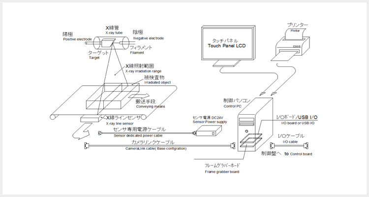
X-ray line sensor camera system standard layout drawing
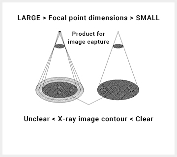 Relation between blur and
focal point of X-ray source
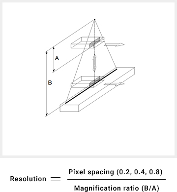 Principle of image magnification

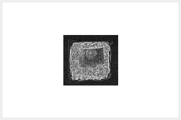
Working example:X-ray image
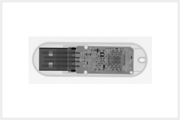 USB memory
 Instant ramen
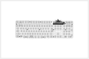 Keyboard
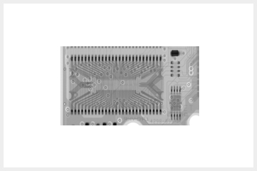 Memory substrate
SAFTY MEASURES
- X-ray safety criteria
- Safety measures for the operator.
This device emits X-rays only within a protective enclosure and moreover the radiation leakage to outside the device is within 1uSv per hour or less to comply with the “Ordinance on Prevention of Ionizing Radiation Hazards” which limits the dosage to 1.3mSv or less over 3 months. This device therefore requires no location having a controlled area (restricted access) and no operation supervisor.
(The business operator planning to use the X-ray device must submit plans for its use to the labor standards inspector having local jurisdiction within 30 days prior to starting device installation work.) - Protection via lead plate
- Protection from exposure to X-ray leakage from this device is generally by means of lead plate attached to the within the interior of this device.
- Protection via lead curtain
- A curtain containing lead is mounted at the entrance and exit to this device. One layer is equivalent to 0.25mm of lead (Pb) and 3 layers are provided.
- Interlock mechanisms
- Mechanisms to swiftly shutoff X-ray emissions shall be installed at all covers, doors and openings. These mechanisms shall also shutoff X-ray emission or prevent X-ray emissions in the event the inspection items become clogged up within the device.
(Interlocks shall automatically stop X-ray emissions and conveyor movement when the event hands or fingers are placed within the conveyor inlet/outlet.)

![Telephone Inquiries|81-53-401-5316[office hours 9AM to 6PM]|Inquiries|sales@imagetech-kk.com](../image/common/aside_contact.gif)
![TEL:81-53-401-5316[受付時間:平日9時~18時]](../image/common/footer_tel.png)